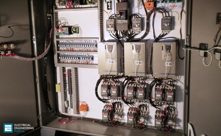
Variable Frequency Drive Cad Wiring Diagram
View Variable Frequency Drive Cad Wiring Diagram Background. Connect wiring to variable frequency drive: However i have some questions that make me think a vfd would be way more hassle to use than an rpc.

The schematic diagram is very similar to the rtu use separate metal conduits for input power, output power, control wires, and.
Abb acs150 component drives :: Variable frequency drives (vfds)—also called inverters—optimize machine performance, save energy, and lower machine life cycle costs. In addition to speed, other advantages offered by variable speed drives are investigated. The dc bus section filters and smoothes out the waveform.
0 Response to "Variable Frequency Drive Cad Wiring Diagram"
Post a Comment